After the power supply was done, I needed a way to interface my board with the existing hardware without blowing up everything.
I am used to low voltage electronics. Putting in a switch is not very difficult as an input: Connect the IO Pin of a MCU to a pull-up or pull-down resistor and let the same pin be shorted to the opposite when a button or switch is operated. Any debounce can be done in the software.
In this case the switch/button is inside a housing that has mains within, which are not isolated. It is easy to make a failure and connect any such input with mains. This would instantly destroy the MCU, which is normally operated at 3.3V instead of the 250Vac.
I needed a way to protect the MCU input pins against this situation.
For this I need to protect the MCU against too much current caused by a too high voltage at the input pins. The mains con not be connected directly to the input pin, which might happen, if someone was connecting the wires wrong. Even for the shortest time, the MCU would be dead before any circuit breaker would even recognize an overcurrent.
Most modern MCUs can cope with overvoltage as long as the current through the pins doesn’t exceed some limit. This is because most modern MCUs have diodes connected between any pin and Vcc/GND that will get shorted as soon as the over- or undervoltage exceeds their forward voltage. You often see max IO voltage specified as Vcc+0.3V as a result from this. These protection diodes are very small and can only take small amounts of current before they blow, but it is often enough to protect them from static discharge.
My target MCU, the CC2538 does have these diodes built in:
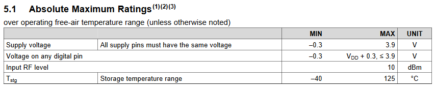
Most datasheets do not specify the current ratings of these diodes, as they are added for ESD protection and not designed for general purpose.
If these diodes are not present in an MCU or their rating is too low for your application you can use external diodes to route under- or overvoltage around the MCU.
I can do this to the input manually. If I take a very high resistor, I can limit the current to a sub-mA even for a 350V input:
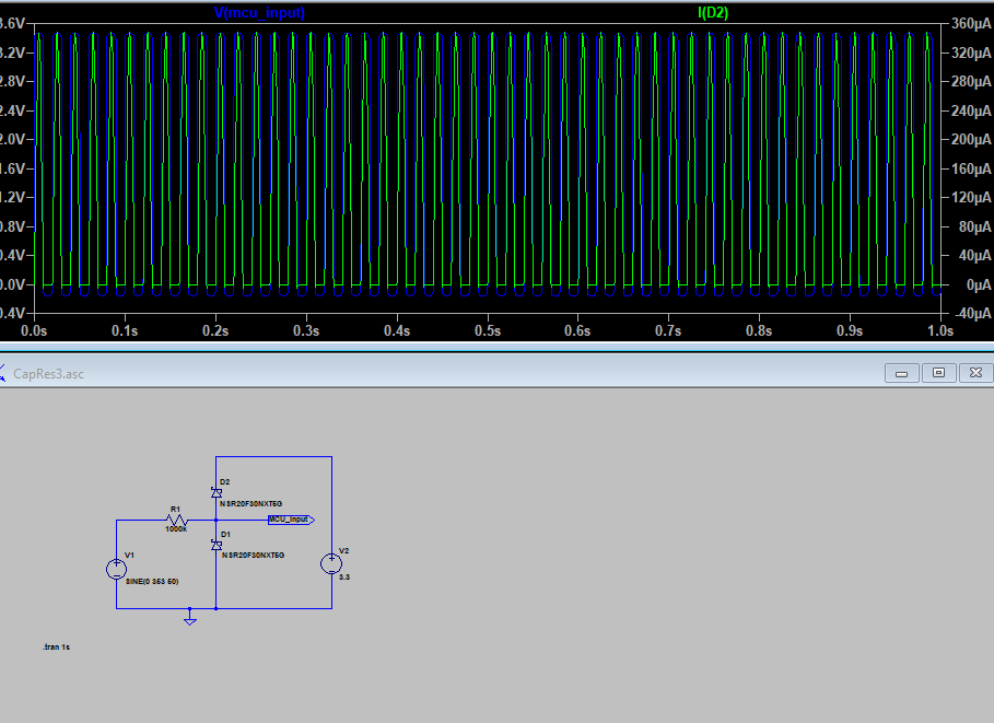
You can see that, if connected to mains phase, the input will be seen as a 50Hz rectangular signal at the MCU input pin and it won’t exceed any current ratings with 350uA. If instead the input is connected mains neutral, the input pin will see a constant low level.
I don’t want to connect the input to mains phase, but now I safely can. Instead i want to connect a switch to mains neutral (ground) and a pullup to the input:

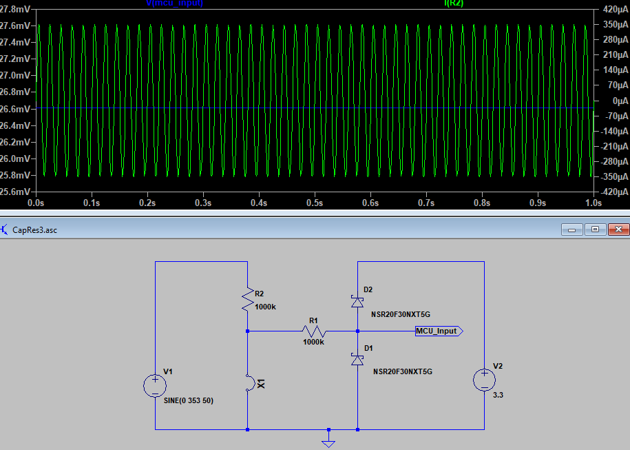
I can now detect an open or closed switch by the detection of a 50Hz signal and it is 250VAC tolerant, so a failure to wire it up does not destroy the board.