Designing a mains powerd BLE/ZigBee Device – Part 2 – 250VAC tolerant MCU input

After the power supply was done, I needed a way to interface my board with the existing hardware without blowing up everything.

I am used to low voltage electronics. Putting in a switch is not very difficult as an input: Connect the IO Pin of a MCU to a pull-up or pull-down resistor and let the same pin be shorted to the opposite when a button or switch is operated. Any debounce can be done in the software.
In this case the switch/button is inside a housing that has mains within, which are not isolated. It is easy to make a failure and connect any such input with mains. This would instantly destroy the MCU, which is normally operated at 3.3V instead of the 250Vac.

I needed a way to protect the MCU input pins against this situation.

For this I need to protect the MCU against too much current caused by a too high voltage at the input pins. The mains con not be connected directly to the input pin, which might happen, if someone was connecting the wires wrong. Even for the shortest time, the MCU would be dead before any circuit breaker would even recognize an overcurrent.
Most modern MCUs can cope with overvoltage as long as the current through the pins doesn’t exceed some limit. This is because most modern MCUs have diodes connected between any pin and Vcc/GND that will get shorted as soon as the over- or undervoltage exceeds their forward voltage. You often see max IO voltage specified as Vcc+0.3V as a result from this. These protection diodes are very small and can only take small amounts of current before they blow, but it is often enough to protect them from static discharge.
My target MCU, the CC2538 does have these diodes built in:

Most datasheets do not specify the current ratings of these diodes, as they are added for ESD protection and not designed for general purpose.
If these diodes are not present in an MCU or their rating is too low for your application you can use external diodes to route under- or overvoltage around the MCU.
I can do this to the input manually. If I take a very high resistor, I can limit the current to a sub-mA even for a 350V input:

You can see that, if connected to mains phase, the input will be seen as a 50Hz rectangular signal at the MCU input pin and it won’t exceed any current ratings with 350uA. If instead the input is connected mains neutral, the input pin will see a constant low level.
I don’t want to connect the input to mains phase, but now I safely can. Instead i want to connect a switch to mains neutral (ground) and a pullup to the input:

I can now detect an open or closed switch by the detection of a 50Hz signal and it is 250VAC tolerant, so a failure to wire it up does not destroy the board.

Designing a mains powerd BLE/ZigBee Device – Part 1 – Power Supply

Some years ago my wife and me added some more space to our house. When planning we added several main power connections to the new rooms and wired a KNX cable beside any mains cable.

This is really nice. It made cabling the mains pretty simple as you only needed to route the mains to any consumer and the KNX (Wikipedia: KNX) also to any switch. It greatly reduced the cables needed even if designed for more total power consumption. Instead of a tree-layout of the cabling we have a trail for each of the power domains.
This is possible as the switches do not directly switch the power to i.e. a lightbulb, but send a command at the lightbulb’s socket to turn on or off that bulb. This works great and allows to control the lights or shutters from multiple locations without creating a cross-switch circuit.
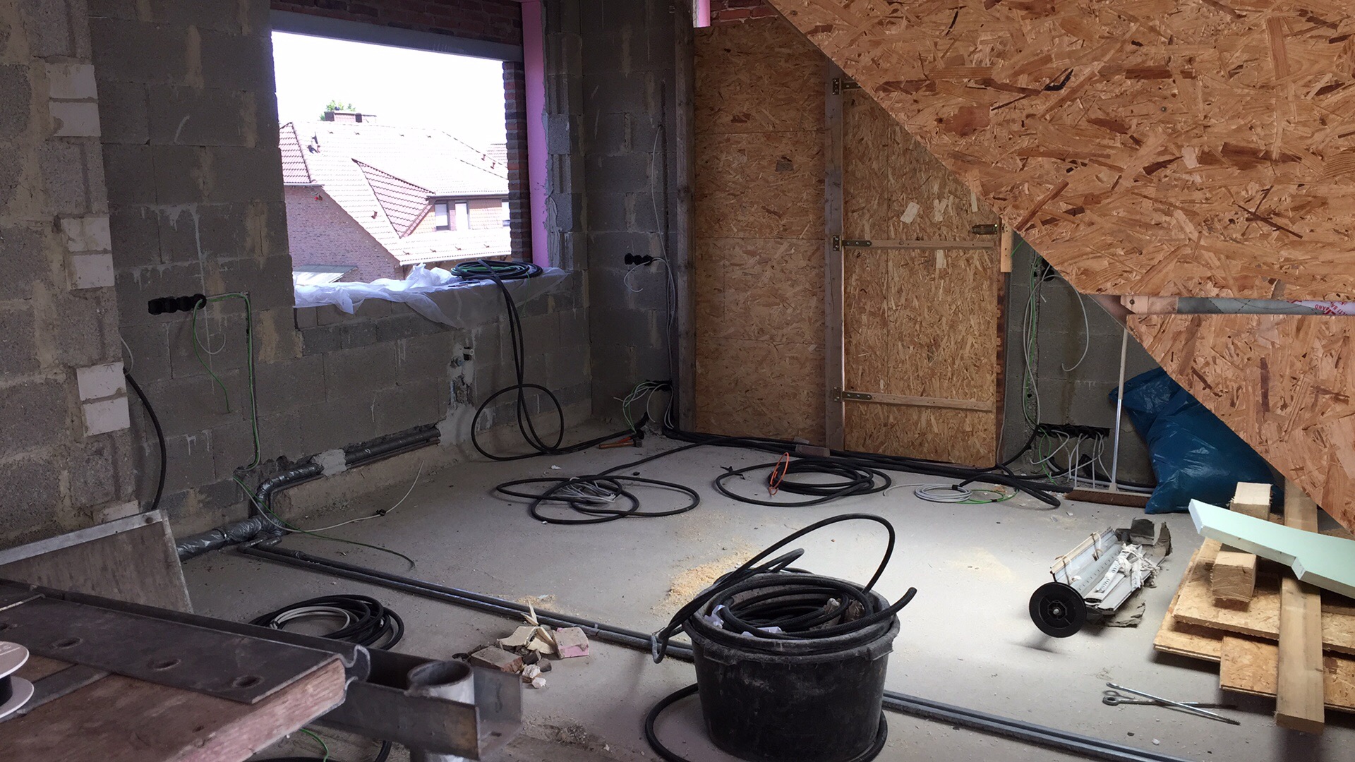
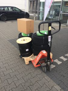
Yet we used a lot of NYM cable and well the green twisted pair to control the KNX:

To make the installation more comfortable we have a KNX to ethernet bridge, which routes the KNX Packets into a protected WLAN. This is not reachable from the outside or by any other unprotected ports or WLANs. This allows us to turn off any light or move any shutter with our smartphones if we are logged in at home.

Since this is an old house we extended, these nice features are only within the new parts. Any light and any shutter in the old part of the house can only be operated at the existing switches.
We would like to change that but don’t want to open up all walls and add new cabling for the KNX control – again.

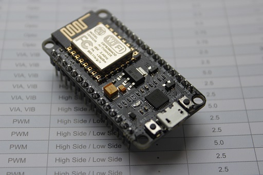
To archieve that I designed a little board to control mains power and to send control packets to through the KNX network to the designated target via ZigBee. This board will have to be placed in all the switches that shall be used as control or to be controlled by KNX.
To make things difficult, all old connections are routed through pretty small housings. A switch or outlet is sitting inside a 50mm diameter, 39mm deep housing, occupied almost completely by the outlet or switch. This leaves only about 10mm of depth and about 43-44mm diameter, so the wires will not be blocked by the new electronics.

My requirements are:

  • Fit into 43mm diameter x 10mm depth
  • Switch (lights only for now) 1 phase of 250VAC, max 1kW
  • Detect state of an existing 250VAC rated, mechanical switch
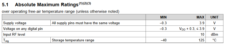
  • Be 250VAC tolerant on any input, yet allowing the switching input to be operated at an IO voltage of 3.3V

The size requirement was an immediate backlash, as I was planning to add a small transformer to be mounted on the PCB, but the smallest I could find were ~15mm in height. This was a no, since i would have to open up the wall to fit it in deeper – something neither me nor my wife wanted.

Cheap chinese electronics often use a capacitive resistance on the mains to drive LEDs. This method is very very unsafe if it is anywhere exposed to human touch, as mains is used as ground either after a bridge rectifier or even simpier, plain from one of the mains lines. This is not of any concern to me, as the board will be mounted behind a mains switch with 250VAC lines that are not even insulated i.e. at screws.
But what if any electrician would need to maintain the switch after we no longer were. He wouldn’t expect a board hanging behind a switch and may touch the board without protection and be electrocuted. The board has to be embedded into a casing of some kind.
3D-Printing to the rescue, a small case is done pretty quick. It has to be printed with a fire-retardant material.

Well that leaves me with even less space to put the electronics into. 42mm diameter and max 8mm height is the new limit.

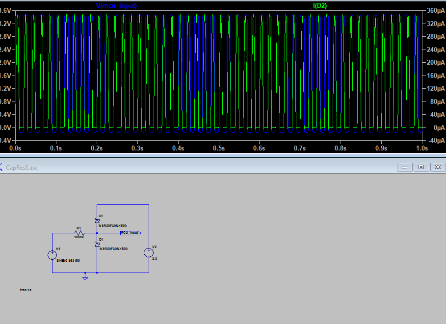
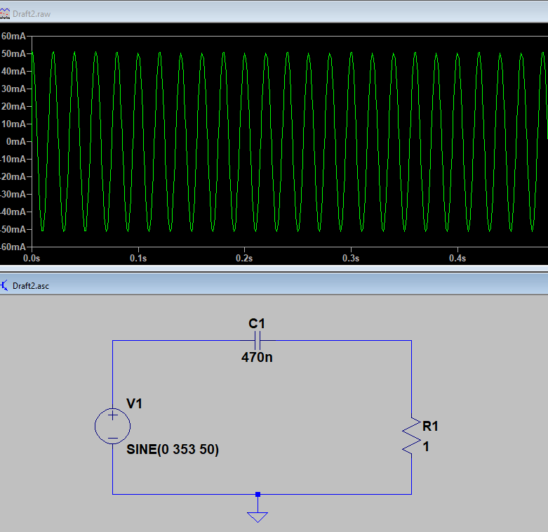
The capacitive coubled power supply is pretty simple. A capacitance is used with its frequency dependend reactance. The frequency of the mains network is well knwon and very stable (50Hz @230Vrms, ~353Vpp here). We can calculate the required capacitance to allow only the required current.

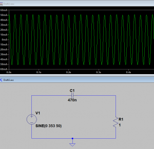
With rectifying and a Zener Diode which is able to limit the voltage for that current we can stabalize the voltage and can supply it to the board. I.e. as shown below to 4.7V @ the same 35mA as above.

Sounds great. There are traps: The mains contains more than the 50Hz alone. Whenever anything is turned on or off, when inductive or capacative loads are used in the mains network, we have spikes and other dirt on the mains. That happens a lot.
In europe we have a standard that defined what the maximum dirt is on the mains for each frequency range. Mostly that is multiple of the 50Hz. For things like power line communication that can be some 10s of MHz and more.
This is a problem fro the reactance since it is frequency dependend. The higher the frequency, the lower the resistance. Leaving me with sub-Ohm resistances for the 100s MHz range. The power of any PLC would go straight into my cirquit.
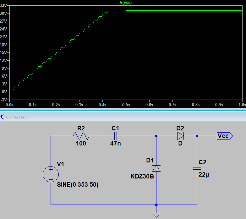
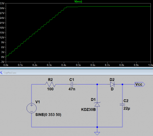
To counter that I added a normal resistance into the path of 100Ohms. Given a load of ~5mA this would lead to 250mW to be dissipated at heat. This is greatly reducing the effectiveness. But on the other side any 100s MHz signal would now also be dampered by 100Ohms driving much less power into the cirquit itself.

Because of the loss at this added resistor, I better not draw too much current. The loss is calulcated as P = U*I. Since U is determinated by the resistor at the working current, P = (R*I) * I. This means double the current double the loss.
I need to drive a CC2538 for the zigbee. It has a max current draw of 35mA at 3.3V. This would be a loss of 100*0.035*0.035 W = 122mW … that is a lot, given that I only consume 115mW in the zigbee part, I have less than 50% efficiency.
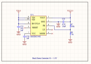
I can reduce the current through the 100Ohms by using a step-down converter to generate the 3.3V. If I need 35mA at 3.3V I would need only 3.5mA at 33V, plus the loss because of the step-down converters efficiency. But at all around a decade less.

With 3.5mA the resistor now only dissipates 1.1225mW of heat. Great!

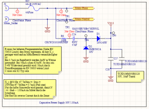
There is another problem. Remember that there are two methods to run the capactivive power supply? One with a bridge rectifier and one connecting the ground directly to one of the mains wires? Well I want to switch an output. I could do this either by a relais, or by a triac. The relais takes up a lot of space. Something I don’t have. So I need to drive a triac. And for that I need a defined current flow from the control to one side of the triac, which is one of the mains. If I would use a bridge rectifier, the voltage between ground and the mains line would jump from 0 to 250V depending on the mains phase. Another NO-GO.

Instead using the simple approach on the rectifying leaves the ground on the same level with one of the mains wires.

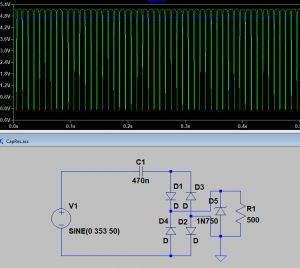
The capcative source now looks like

WARNING: Ground is directly connected to a mains wire. Touching Ground or any other connection composes a lethal danger.
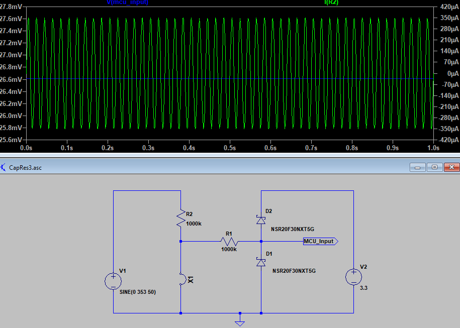
As you see, only half of the sine is used by this simple rectifying method. This leaves us only with half the current over a full period. This will no longer be able to continously supply 35mA @ 3.3V for the ZigBee chip. But I won’t need it continously. Most of the time the CC2538 will be in sleep mode, awaking every now and then to send and receive commands.

You have seen that the capacitance C1 is the key to limit the current flowing through the cirquit. If this capacitance fails with a short, the full 250Vac will be routed through the cirquit and destroy it. C1 must be of a type that will fail as a open cirquit, so that if it will fail – and it will fail someday – it won’t take everything with it. Select a X2 type of capacitance here.

There are only few X2 types for surface mounting with a small footprint. 47n are about the limit right now. For higher capacitances and therefor currents I would need to use bulky through holes one. Phew!

This leads up to the following supply cirquits:

Analysis of the network protocol used by a Mirai variant – Part 1 – Credential list

I recently digged into some malware analysis and started with something that seems to be simpe to catch and analyse.

This is part 1 of the analysis of a Mirai variant:

Analysis of the network protocol used by a Mirai variant – Part 1 – Credential List

Please leave critics 🙂

An update to mDNS (Querries, yay!)

It’s been a week since the last blog post about mDNS and the nodeMCU.
I’ve promised further updates and well here they are.

The bonjour user module can now question other mDNS / bonjour devices for their IP and other info.

A lot has changed in the API, and some more changes will come, but i hope to have covered the major things now. As it is now:

  • requests, responses = bonjour:parse(frame)
    

    will now return request and responses. Some responses are completely parsed (Type A, CNAME and SRV) more types are to come

  • bonjour:create_request({request1, request2, ..})
    

    now generates a mDNS frame containing the requests. A request itself is a table with name, type and class fields. I.e.

    request1 = { name="domain-name.local", type=bonjour.TYPE.A, class=bonjour.CLASS.IN }
    
  • bonjour:create_response({response1, response2, ..})
    

    now generates a mDNS frame containing the requests. A request itself is a table with name, type, class, and ttl filled. I.e.

    response1 = { name="esp-8266.local", type=bonjour.TYPE.A, class=bonjour.CLASS.IN, ttl=64, ip=wifi.sta.getip() }
    
  • Depending on the type, also (A): ip, (CNAME): cname, (SRV): host, port, priority and weight must be present.

  • to fill the fields,
    bonjour.TYPE
    

    and

    bonjour.CLASS
    

    contain the required constants. Named as in RF1035. I.e. bonjour.TYPE.A

  • the field
    bonjour.VERSION
    

    contains a version id (16bit, high byte = mahor, low byte = minor version)

So what?
Querries! 🙂

Want to find other nodeMCU devices running the mDNS responder or your Fruit-Branded Smartphone? Just ask them for their IP now.
mDNS_request_answer

The source file of the bonjour module can be found here.
I have added an extended version of the same mDNS responder lua file for the latest Demo Firmware I had provided with the last demo:

if ((bonjour ~= nil) and (bonjour.VERSION >= 0x0002)) then
  bonjourRequestIP = {}

  if (wifi.sta.getip() == nil) then
    print("mDNS requires an ip address. Please connect to a station.")
  else
    srv = net.createServer(net.UDP)
    conn = net.createConnection(net.UDP, 0)
    conn:connect(5353, "224.0.0.251")
    srv:on("receive", 
    function (s, c)    
      -- get requests from frame
      requests, responses = bonjour:parse(c) 
      if (requests ~= nil) then
      for index, request in pairs(requests) do
        tmr.wdclr() ;
        print("Request mDNS["..index.."]: "..request.name.."(Type: "..request.type..")")
        if ((request.name:lower() == "esp-8266.local") and (request.type == bonjour.TYPE.A)) then
        conn:send (
          bonjour:create_response({{name = request.name, type=bonjour.TYPE.A, class=1, ttl=64, ip=wifi.sta.getip()}})
        )
        end
      end
      end
      if (responses ~= nil) then
      for index, response in pairs(responses) do
        tmr.wdclr() ;
      if (response.type == bonjour.TYPE.A) then
        if (bonjourRequestIP.Name ~= nil) then
          if (bonjourRequestIP.Name:lower() == response.name:lower()) then
            bonjourRequestIP.IP = response.ip
            bonjourRequestIP.Callback(response.ip)
            bonjourRequestIP.Name = nil ;
          else
            print("Response mDNS["..index.."]: "..response.name.."(A: ip="..response.ip..")")
          end
        else
          print("Response mDNS["..index.."]: "..response.name.."(A: ip="..response.ip..")")
        end 
      elseif (response.type == bonjour.TYPE.CNAME) then
        print("Response mDNS["..index.."]: "..response.name.."(CNAME: cname="..response.cname..")")
      else
        print("Response mDNS["..index.."]: "..response.name.."(Type: "..response.type..")")  
      end
      end
      end
    end
    )
    srv:listen(5353)
    net.multicastJoin(wifi.sta.getip(), "224.0.0.251")
  end
  
  
  function RequestBonjourIP(localname, callback)
    bonjourRequestIP.Name = localname
    bonjourRequestIP.Callback = callback
    bonjourRequestIP.IP = ""
          bonjourRequestIP.Retry = 0
    bonjourRequestIP.Done = 0
    conn:send(bonjour:create_request({{name = bonjourRequestIP.Name, type = bonjour.TYPE.A, class=bonjour.CLASS.IN}}))
    tmr.alarm(0,300, 1, 
      function()
        if (bonjourRequestIP.IP == "") then
          if (bonjourRequestIP.Retry > 8) then
            bonjourRequestIP.Done = 1
              bonjourRequestIP.Callback(nil)
            tmr.stop(0)
          end
          conn:send(bonjour:create_request({{name = bonjourRequestIP.Name, type = bonjour.TYPE.A, class=.CLASS.IN}}))
          bonjourRequestIP.Retry = bonjourRequestIP.Retry + 1 ;
        else
          bonjourRequestIP.Done = 1
        end
      end
    )
  end
  
else
  print("mDNS Server requires user module Bonjour v0.02 or higher.") ;
end

A lot of error checking was added and more will be done.
There might be crashes with huge mDNS requests (i.e. a 1010 byte request a local device sends sometimes here seems to trigger a reset) but further investigation is required to rule out that this is simply the watchdog for taking too long or if the request is using up too much memory.

Several mDNS response formats need to be parsed. right now they will be sent and received ignoring their actual payload.

This leaves me to say:
Have fun!

Name resolving demo / mDNS reponder

I have cleaned up the mDNS request parser and completed some local tests.
There are still some things open to fullfill the mDNS RFC but for now it works.

So I am posting a nodeMcu firmware built with the bonjour module and a simple demo.
It was tested on a nodeMcu Devkit V1.0 based on the ESP-12e:

What you will need:

Step 1:
Extract the .bin files from the .zip
Load the firmware on your NodeMCU (see Setting up a ESP8266 Build environment)

Step 2: Upload the LUA files
Extract the two Demo Files from the .zip
Use the LUA Loader to copy both files onto the nodeMCU

Step 3: Execute the LUA files
For mDNS resolving you need only to execute (dofile) the mdns_server.lua. If you want to see a html page opening in a browser, also execute the httpsrv.lua

Step 4: Showtime
You can now either ping your esp under the address esp-8266.local or open your favorite web-browser and open the webpage http://esp-8266.local/

„Name resolving demo / mDNS reponder“ weiterlesen

Creating a new NodeMcu User-Module

You can do many things with the LUA scripting language on the NodeMCU.
Sometimes however you want to to parts of the work in C code for various reasons.

The nodeMcu developers have found quite a usefull way for you to implement own modules to extend the API with your own C code.

This little how-to will create a small user module named bonjour.
At first we will only do a little “Hello World” example from this module. In a later blog post I intend to extend this module to a minimalistic mDNS responder to resolve your esp-8266 only by using it’s bonjour name instead of a difficult to remember and ever changing IP address.
„Creating a new NodeMcu User-Module“ weiterlesen

Setting up a ESP8266 Build environment

The ESP-8266 is a neat little µC with an 802.11b/g/n interface built in (Wikipedia).
You can buy this µC on various little boards. I did so myself with a nodeMcu devkit board, which includes bower supply throuigh USB and an USB serial port converter.

This description therefor will orient itself around the nodeMcu board but shall also apply to the other ESP8266 boards.
The how-to is done from memory. I hope i have caught all steps and traps. If not or you have difficulties following the instructions, please leave a comment.

What you will need:

Step 1: Prepare drivers
Download and install the driver package for the USB-to-serial driver.

Step 2: Prepare the VM Host
Download and install Virtual Box

Step 3: Prepare the VM Guest
Download the official SDK VM

Step 4: Install the VM
Start Virtual Box.
From the menu, chose File -> Import Appliance.
In the dialog, browse to the official SDK VM (.ova file) and follow to the next step.
Now you should see the parameters of the new VM listed. If everything looks OK (should be) then just hit import.

Step 5: Configure file exchange
Create a folder you want to use to share the source code files between your PC and the VM. i.e. C:\VM\Share.
In Virtual Box right click on the newly imported VM and select the first menuitem: change.
Navigate to “Shared folder”.
Shared_Folder_1
Click on the existing share and use the context menu to get into the change dialog.
Change the folder path to your created folder and make sure the folder. Hit OK when you are done and exit the change dialog.
Shared_Folder_2

Step 6: Prepare the version control software
Install TortoiseGIT

Step 7: Prepare the source code
Use your file explorer and navigate to your shared folder.
Right click on the folder’s empty background and select “Git Clone”.
Clone the repository “https://github.com/nodemcu/nodemcu-firmware.git”
Git CloningGit Cloning 2Git Cloning 3

Step 8: Prepare compilation
Start up your virtual machine.
It will greet you with a linux desktop and a single symbol at the top left corner. Execute this program “LX Terminal”
ESP8266_lubuntu
Mount the shared folder by typing “./mount.sh” into the opened terminal. The password it will ask you for is “espressif” (without the quotes).
ESP8266_lubuntu_2
Now you can move into the shared folder and into the firmware repository by “cd Share/nodemcu-firmware” make sure to use the correct casing.

Step 9: Configure modules /libraries
Comment in any module defines you want to have in your build in app/includes/user-modules.h and comment out all #defines of modules you don’t want to have in your buid.

While trying to compile the nodeMCU firmware as is from the source, I had errors locating the math library. As I do nit use the math library, I have deactivated the -lm linker option:
Open the app/includes/user-modules.h and comment out the #define LUA_USE_BUILTIN_MATH
Open the Makefile in the root app folder and change the linkflags from

LINKFLAGS_eagle.app.v6 = 			\
	-Wl,--gc-sections 			\
	-Wl,-Map=mapfile 			\
	-nostdlib 				\
	-T$(LD_FILE) 				\
	-Wl,@../ld/defsym.rom			\
	-Wl,--no-check-sections 		\
	-Wl,--wrap=_xtos_set_exception_handler	\
	-Wl,-static 				\
	$(addprefix -u , $(SELECTED_MODULE_SYMS)) \
	-Wl,--start-group 			\
	-lc 					\
	-lgcc 					\
	-lhal 					\
	-lphy 					\
	-lpp 					\
	-lnet80211 				\
	-lwpa 					\
	-lmain 					\
	-ljson 					\
	-lsmartconfig 				\
	-lssl 					\
	$(DEP_LIBS_eagle.app.v6) 		\
	-Wl,--end-group 			\
	-lm

to

LINKFLAGS_eagle.app.v6 = 			\
	-Wl,--gc-sections 			\
	-Wl,-Map=mapfile 			\
	-nostdlib 				\
	-T$(LD_FILE) 				\
	-Wl,@../ld/defsym.rom			\
	-Wl,--no-check-sections 		\
	-Wl,--wrap=_xtos_set_exception_handler	\
	-Wl,-static 				\
	$(addprefix -u , $(SELECTED_MODULE_SYMS)) \
	-Wl,--start-group 			\
	-lc 					\
	-lgcc 					\
	-lhal 					\
	-lphy 					\
	-lpp 					\
	-lnet80211 				\
	-lwpa 					\
	-lmain 					\
	-ljson 					\
	-lsmartconfig 				\
	-lssl 					\
	$(DEP_LIBS_eagle.app.v6) 		\
	-Wl,--end-group 			

 
Step 10: Deactivate serial module in esptool.py
Since we will be using the ESP Flash Tool on windows, we will deactivate the serial module on the last build-step:
Open tools/esptool.py and remove the line

import serial

as would only produce errors on the stock VM.

 
Step 11: Compile
Create your first build from stock nodemcu firmware:
“make”
This will take some time on the first run. Subsequent builds will only compile the changed and dependend files.
ESP8266_lubuntu_3
If everything continues without errors, there should be now two binary files in the nodemcu-firmware/bin folder. This is the actual firmware to flash on your nodeMcu/esp8266
Output

Step 12: Flash to device
Now connect your nodeMcu with the USB-Micro cable to your PC.
Start the ESP Flasher Tool. Select the COM Port of the nodeMcu (if you don’t know it, you can look it up in the system properties under device manager)
Activate the config tab.
Mark the first two lines and select the two binaries you created in Step 9. In the corresponding address fields on the right, select the number matching the binary’s name.
Flasher Config
Go back to the first tab and hit Flash!

The nodeMcu will start blinking and the progress bar will run through twice.
Reset the nodeMcu (hit the little RST button) and have fun!

PS: If you encounter any issues, please leave a note and I will try to solve them in this little how-to.